|
Excavation and Foundation |
|
| 
|
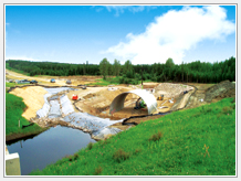
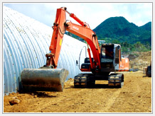
When excavating the ground to prepare
the foundation, the excavating slope should be 1:1 or 1:1.5
and, if the slope is high, a bench should be prepared for
stable slope.
The width of a bench should be about 3.0m; the width of
excavating bottom should be larger than the width of steel
structure by at least 3.0m; excavating depth should be larger
compared with the position of installed structure by at
least 0.5m; on the stable ground, no replacement is needed
and only hardening process performed. Things regarding soil
cut and hardening shall conform to the related regulations
of domestic specifications.
|
|
| |
|
Bedding |
|
| Bedding is essentially required for foundation of
circular structures and plays the role of a cushion between
the foundation and steel material; the material same as
the basic material should be used and loosened and fine
sands should be sprayed to the about 70-100mm of space
contacting with steel plate so that the wave of steel
plate may closely contact with the bed.
Corrugated steel plate is the one that anticorrosive property
is improved with galvanization; care should be taken to
avoid possible scratch of the surface; after installation,
no rough gravel should be used in the space contacting
with steel plate and bed.
The thickness of bed should be about 60cm from the lower
end of steel plate; the material same as the foundation
should be used in hardening; the part adjacent to steel
plate should be lightly hardened using the sand/gravel
(1/2 of the wave size of steel plate) or sand.
The width of bed should be similar with the distance between
the parts where curvature radius is changed and, in case
of circular structures, the bed should be formed with
the margin that hardening of the haunch of steel plate
is not difficult. Bedding is more required when the curvature
of lower steel plate is large; as hardening the haunch
is difficult, the bed should be formed to meet the curvature
radius so that construction may easily be performed.
|
|
| |
|
Foundation of Bridge Plate |
|
| 
|
Bridge Plate is built on the concrete
foundation consisted of C-shaped base channels and anchor
bolts. In case of open cross section (arch-type cross section),
the foundation concrete structure should be installed at
the accurate position to support the steel plate walls and
the distance between anchoring channels should be confirmed
with measurement.
- Steel plates and foundation concrete are connected using
anchoring channels.
- Anchoring channels are installed with burying anchors
before spraying concrete and, after spraying concrete, anchored
connection angles may be used.
- Anchoring channels should be connected with steel plates
at a right angle. |
| |
|
| |
|
| |
|
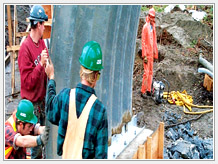
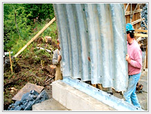
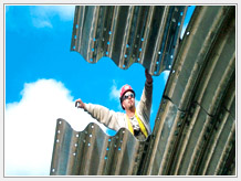
Assembling and Installation of Bridge
Plate |
|
| 
|
Fixon manufactures Bridge-plate under
the strict quality control; the produced panels are packaged
in sets for convenient construction work; and the parts
to be assembled are packaged in separate boxes and supplied
to the site.
As each Bridge-plate has printed number on its surface according
to the assembling sequence so that classification and assembling
may easily be done; the detailed specifications supplied
with installation design together have detailed information
on construction to help rapid construction work.
Panels may be partially assembled and then may be moved
to the installation site for connection and construction
work at the site, to meet the situation of the site.
As assembling method may be different depending upon the
situation of site, the method should be decided through
discussion with the field supervisor or representative.
|
| |
|
| |
Details of overlapped bolt
for connection of corrugated steel plates
[Brief drawing of details of Bridge Plate assembling] |
|
| |
|
Final Treatment |
|
| 
|
In order to prevent distortion or damage to
the tip of the structure, we treat the tips with concrete
to keep shape of the angle or the structure. The treatment
of overlapped panels also reinforces the structure. |
|
| |
|
Headwall options |
|
| - Concrete cast
- precasted concrete panel
- piled panel
- stoney breast wall
- Gabion
- Corrugated steel plate
Headwalls treated with impervious materials prevent the
entrance ground from erosion and blocking.
|
|
| |
|
Backfill |
|
| 1) Materials for backfilling must be same as the
aggregate described on the specification.
- Materials should be febbles, sands, slag, and shattered
stone which are strong and durable and the mixed aggregate
proved by the inspector and silt. The materials should
not contain the impurities and must be qualified. Materials
should be in regular shape. If you want to change or alter
the materials, approval from the inspector is needed.
SB-1 qualification |
| Section |
Test method |
Criteria |
| Liquid limit |
KS F 2303 |
Less than 25 |
| Less than 25 |
KS F 2508 |
Less than |
| Abrossion loss |
KS F 2304 |
Less than |
| Plasticity(%) |
KS F 2320 |
Over 30 |
| Sand equivalent value of soil |
KS F 2340 |
Over 25 |
|
But, the CBR of the SB-1 should be more than 80
|
| - Selecting Materials
Before choosing materials for SB-1, purchaser should get
permission from the inspector.
Purchasing Subbase Course |
| Purchase number |
permiability |
| 100mm |
75mm |
53mm |
37.5mm |
19mm |
4.75mm
(No.4) |
2.0mm
(No.10) |
425㎛
(No.40) |
75㎛
(No.200) |
SB-1
SB-2 |
|
100 |
-
100 |
70-100
80-100 |
50-90
55-100 |
30-65
30-70 |
20-55
20-55 |
5-25
5-30 |
2-10
2-10 |
|
| |
Backfilling material
The size of backfilling materials within the 300mm
from the structure should not exceed 75mm
|
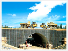
| Backfilling process |
- Heavy equipment handlers should follow the work range
by the technician to avoid the impact from the equipment.
- Unloading backfilling material on the upper part of the
structure is prohibited but on the lateral part.
- Use compacting machine to compact the soil.
- Trucks or heavy equipment should be away from the distance
from the structure that is proposed by specification.
- Thickness of layer compacted by vibrating machine should
be less than 200mm. In order to lessen the longitudinal
impact from the end of the structure, compacting machine
should keep away from the end of the structure.
- No access of truck within 1500mm from the side of the
structure is permitted.
- Backfilling layers should be compacted one by one, in
an order of “left and right” or “right and left”, The gap
of the left and right layer thickness should not be over
400mm.
|
| 
|
| 3. Compaction. |
| - Use a vibrating machine or portable compacting machine
to compact the soil in a longitudinal way.
- Backfilling material should contain appropriate amount
of water retention according to the specification.
- Compaction density of each layer is at least 95%.
- Accessibility of the upper part of the structure.
|
| 4. Accessibility of the upper part of the
structure |
 |
- Regarding backfilling at the 3/4 height
of Rise, backfilling materials are unloaded on the
crown part of the structure and start backfilling
across the structure.
- Backfilling of the upper part of the structure
must be done under the supervision of the instructor.
- There is non-compaction area of 600m between the
upper part and the equipment on both sides of the
structure.
- The equipment for unloading backfilling materials
should not be heavier than D-4 caterpillar dozer,
which is 7 metric tons. Compacting equipment should
not be heavier than BWW-775.
- Thickness of layer compacted by vibrating machine
should be less than 200mm. In order to lessen the
longitudinal impact from the end of the structure,
compacting machine should keep away from the end
of the structure.
|
|
|
| |